
One pass of air. Eight steps.
Air enters at the crown, 300 to 800 feet up. It leaves at the base, cleaned. Everything in between happens inside a tower that runs on power it makes itself.
SCROLL ↓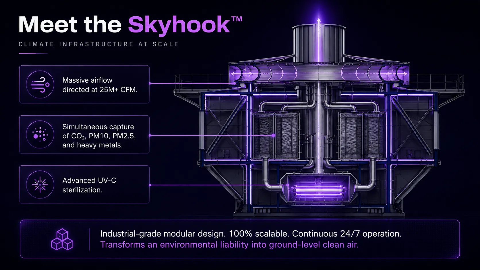
Height is the whole argument.
Conventional direct air capture works at ground level, up to about 100 feet. At that height the carbon is thin, so the machine has to move enormous volumes of air to find it. That takes heavy electricity and water, and the footprint of running it offsets much of what it captures.
LiteAir works higher. SkyHook towers draw from 300 to 800 feet, at the level where pollution actually sits and concentration is far richer. The same pass of air yields more. And because the tower generates its own power from the airflow moving through it, none of that work is borrowed from the grid.
Climate infrastructure at scale.
One SkyHook unit moves air at industrial volume and treats it for everything it carries, carbon, particulate, metals, and pathogens, in the same pass. The design is modular and fully scalable: the same industrial-grade unit that serves a single facility stacks to serve a port, a corridor, or a district.
Follow the air down.
- Air intakeAir enters at the crown of the tower, 300 to 800 feet up, where carbon concentration is at its richest.
- Multi-layer filtrationHigh-efficiency filters remove dust, sand, metals, and pollutants, and begin capturing CO₂. Filters are reusable and regenerated for continuous operation.
- Carbon separationCarbon filters trap CO₂ and harmful gases. Adsorption technology separates the carbon from the air stream.
- Clean air flowPartially purified air continues downward through the tower in a controlled 360 degree circular path.
- Fusion light chamberAir passes through the fusion light chamber, where UV-C and photocatalytic oxidation eliminate bacteria, viruses, mould, and other microorganisms.
- Clean air dischargePurified air is discharged at the base through a 360 degree ventilation system, improving air quality at ground level.
- Carbon recoveryCaptured carbon is converted to gas, then routed to an end use or to permanent storage. The choice is the owner's.
- Measurement and reportingRecovered carbon is metered as it leaves the tower. Onboard sensors verify every ton captured, and the data flows to the owner as auditable reports for carbon accounting and compliance.
Five media. Configured per site.
Not every tower carries all five. A tower on a coastal chemical site and a tower in a sandstorm region do not need the same stack, so each tower's media are selected and specified for the air it will actually breathe.
Engineered to never stop.
Airflow is generated by a high-efficiency blower ring at the tower's base, driving a powerful downward current through vertical-axis turbine generators positioned in high-turbulence zones within the shaft. Vortex rings stabilize and intensify this downward airflow, ensuring consistent throughput even under variable ambient wind conditions, which eliminates dependency on unpredictable natural airflow alone.
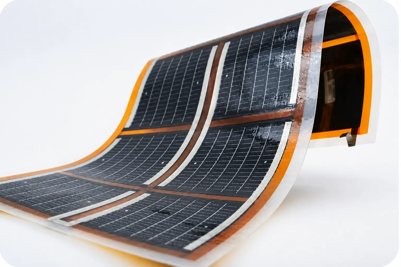
Energy captured by the turbine generators is routed through an internal energy conduit to onboard inverters and storage systems, while flexible thin-film solar laminate integrated across the tower's exterior surface provides a supplemental, continuous charging source. Because all filtration, mechanical, and electrical components are housed within the protected base structure, the system maintains 24/7 operational integrity regardless of weather exposure, with redundant power inputs, turbine-generated and solar, minimizing downtime risk and ensuring uninterrupted air purification output.
Carbon goes somewhere useful.
Captured carbon is converted to gas as stage one. From there it is either processed into a range of end uses or held in permanent storage. LiteAir captures and prepares the carbon. Which pathway it takes is determined by the owner, against their own operational, regulatory, and sustainability goals.